
The LED
Provide an LED light indication for your projects where the brightness and the input voltages can be controlled with the On-board potentiometer.
Introduction
The LED, also known as a Light Emitting Diode, is a component that emits light. The Grove Red LED module is a digital component that uses only the output, not the input. This module can be primarily used for providing visual light feedback in various electronic devices such as remotes, radios, speakers etc.
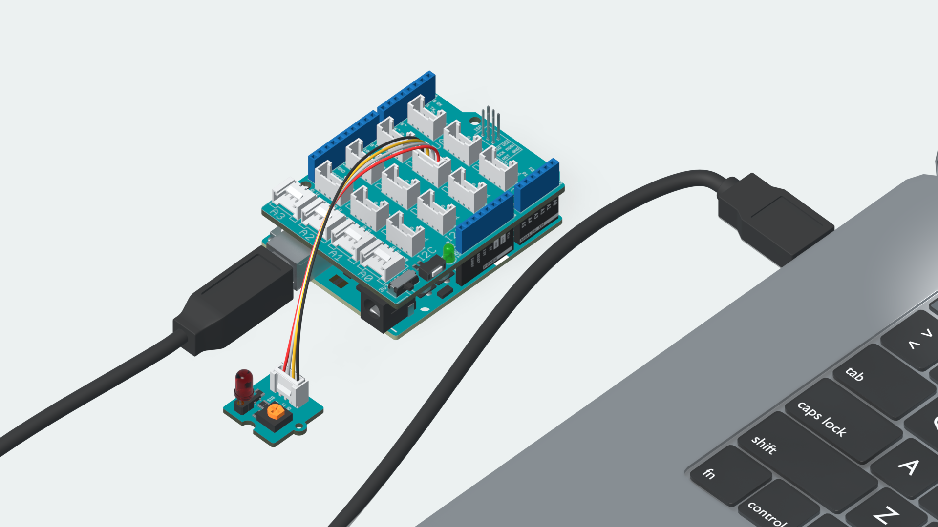
Plug
The Grove LED Module connects to the board through the Digital Pins. Plug in the LED Module to the Digital Pin marked D6 on your Grove Base Shield. Attach the Shield to your Arduino UNO R3 and connect it to your computer.
Sketch
#define LED 6

void setup() {
  // put your setup code here, to run once:
  pinMode(LED,OUTPUT);    //Sets the pinMode to Output
}

void loop() {
  // put your main code here, to run repeatedly:
  digitalWrite(LED, HIGH); //Sets the voltage to high
  - delay(1000);           //Waits for 1000 milliseconds
  digitalWrite(LED, LOW);  //Sets the voltage to low
  delay(1000);             //Waits for 1000 milliseconds
}
Play
Copy the code from the snippet above, into the Arduino Editor of your choice. Choose the right board & port and upload the code to your board.
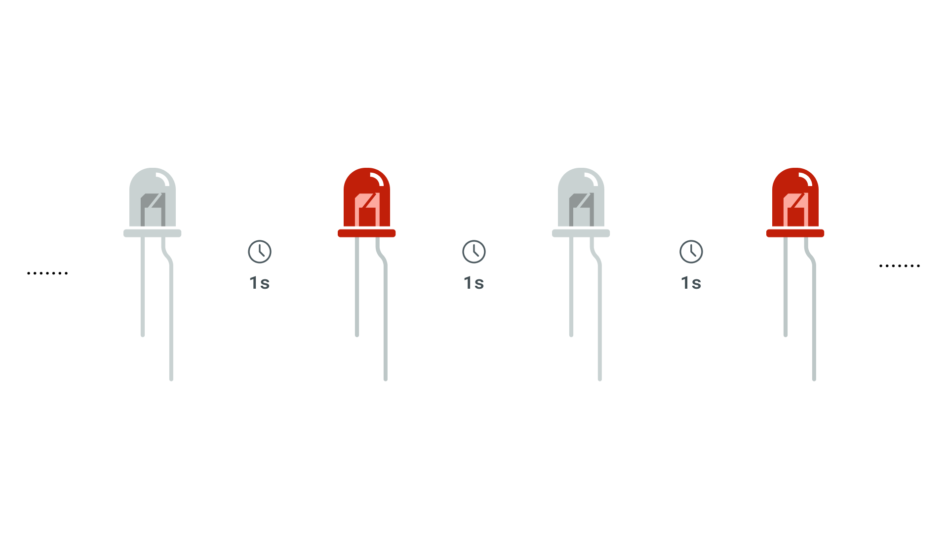
After the code has successfully uploaded, you will notice that the LED starts blinking with an interval of 1 second.
Understand
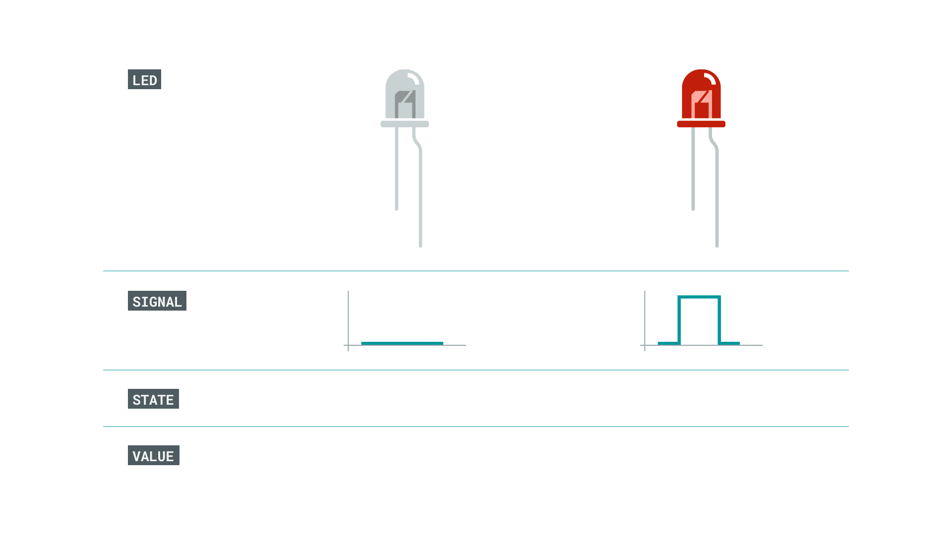
The LED works by sending digital signals. When the signal is high, the LED lights up and when the signal is low the LED is off. We can mimick this behavior through the function digitalWrite().
We use DigtalWrite(LED, HIGH) to send out a 5v current though the digital pin, whereas digitalWrite(LED, LOW) sends out a 0 current. The transition between the ON and OFF stage is controlled by the delay() which in this case is 1000 milliseconds.
You can read more about the following functions and their usage from the references below.